


It's lowkey expected considering how hard it draws from self-help movements
related phenomenon. at calm solar surface, there's only hydrogen and helium. these are excited thermally and can emit radiation, but the highest energy photon they can emit is ca 13eV and 52eV respectively. this is vacuum UV, and this is what is responsible for ionisation of ionosphere even during solar minimum, mostly F layer. but when solar flare forms, there are these giant loops of charged particles, and when charged particles change direction or brake, they release a lot of high energy radiation, that is xrays. xrays just go everywhere and this is partially what is responsible for extra ionisation of ionosphere during solar maximum, and this contributes more to E layer ionisation. (because xrays can go further through air) when solar flare hits the earth, protons from it cause extra ionisation in D layer and this is why post-flare blackouts happen
this is also why one metric of solar activity is solar xray flux
there are also solar xrays, which also ionize ionosphere and are associated with CMEs (regular processes on surface of sun cannot make much xrays, it's only when high energy particles are smashed back at the surface xrays are emitted. intense magnetic fields are needed for that)
Fair. I'm doing synthetic chemistry for a living, and probably i have as much use of electrochemistry or crystallography as you do have of organic chemistry. I get it is a skill with a limited utility, and i might be biased, but i don't get why people complain about it so much. On the other hand, one of my labmates was hired by mat sci lab as a single person fire brigade to unfuck their project, ant it worked despite no organic chemistry involvement
if you don't mind, what field are you in that you were examined in ochem but you don't use ochem? last time i've checked, chatbots crap the bed constantly when asked about anything that you can deduce (easily, by analogy) but can't find, especially as text, the mistakes were either glaring or sneaky but never correct. it's much easier to express what you mean by drawings in ochem anyway
ah yes famously non-far-right cryptobros and downright woke russian and iranian sanction evaders
both alumina and raw aluminum, it's alloyed to spec after smelting
medical chatbot would be malpractice lawsuit pinata
Man brings man to the brink of death, for profit
they had big corporate contracts for their other, boring and profitable part of the business, but that won't save them from openai going broke. it's like 50x less than they need
i have been informed that the faster the company explodes the faster they can iterate, so eventually they'll make company that doesn't explode
and also crypto https://codeberg.org/Codeberg/org/pulls/1254 surviving cryptobros are nonplussed
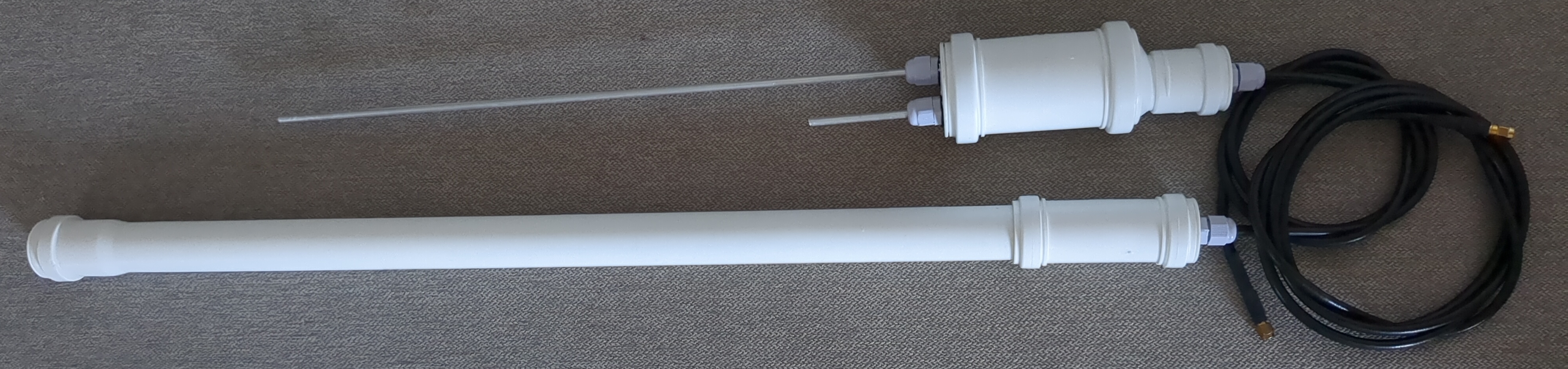
These two are for 70 cm. That's how their outsides look like:

and these are their insides:
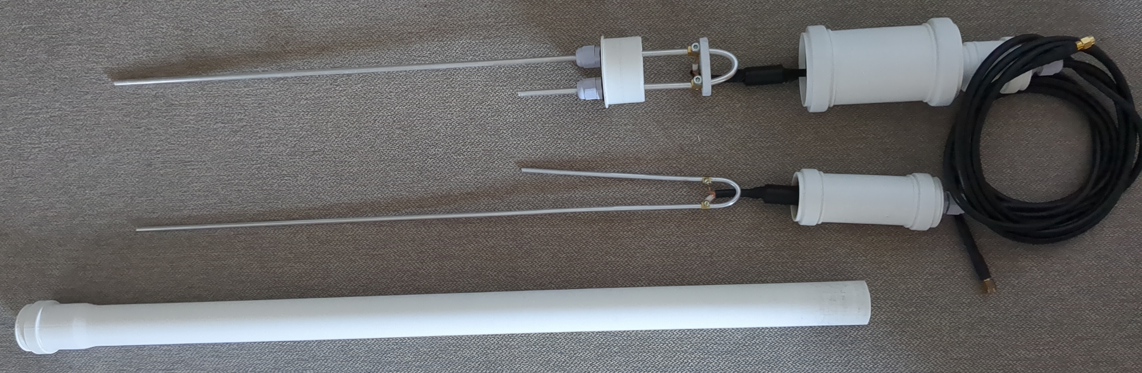
The short tube construction uses 50mm drain pipe barrel connector, 50mm to 30mm reduction, two caps and three cable chokes for chassis. Overall it should be as waterproof as it gets. Wire used is 5mm aluminum wire, it was a bit wobbly when attached only via cable chokes so i've added a bit of plastic (originally cutting board) that loosely fits in the 50mm part of reduction. Electrically, coax is soldered to back side of a wire connecting block sawn in half and screwed to aluminum wire. Because all connections are inside the waterproof enclosure, corrosion shouldn't be a massive problem, and distance between feedpoint and bottom part is so small thati think that this type of construction would be practical even on lower VHF, as long as length of antenna can be dealt with (sectioned radiator maybe?). It also has lower wind loading than the other one. This is how it works:

The long tube construction is a 30mm drain pipe with caps. Wire used here is 4mm aluminum wire, it's springy enough that when inserted into the tube it lies flat against internal surface of tube. Because wires don't stick out no extra fastening is required and it kinda just works. It's probably a bit harder to break than the other one. Both have ferrite beads for common mode current suppression. I think this type of construction should be practical at 70cm and above, up to 1.2GHz band, maybe up to 2.4GHz. Presence of tube shifts resonant frequency down, so measurements have to be made with tube on. This is how it works (length of coax was different):
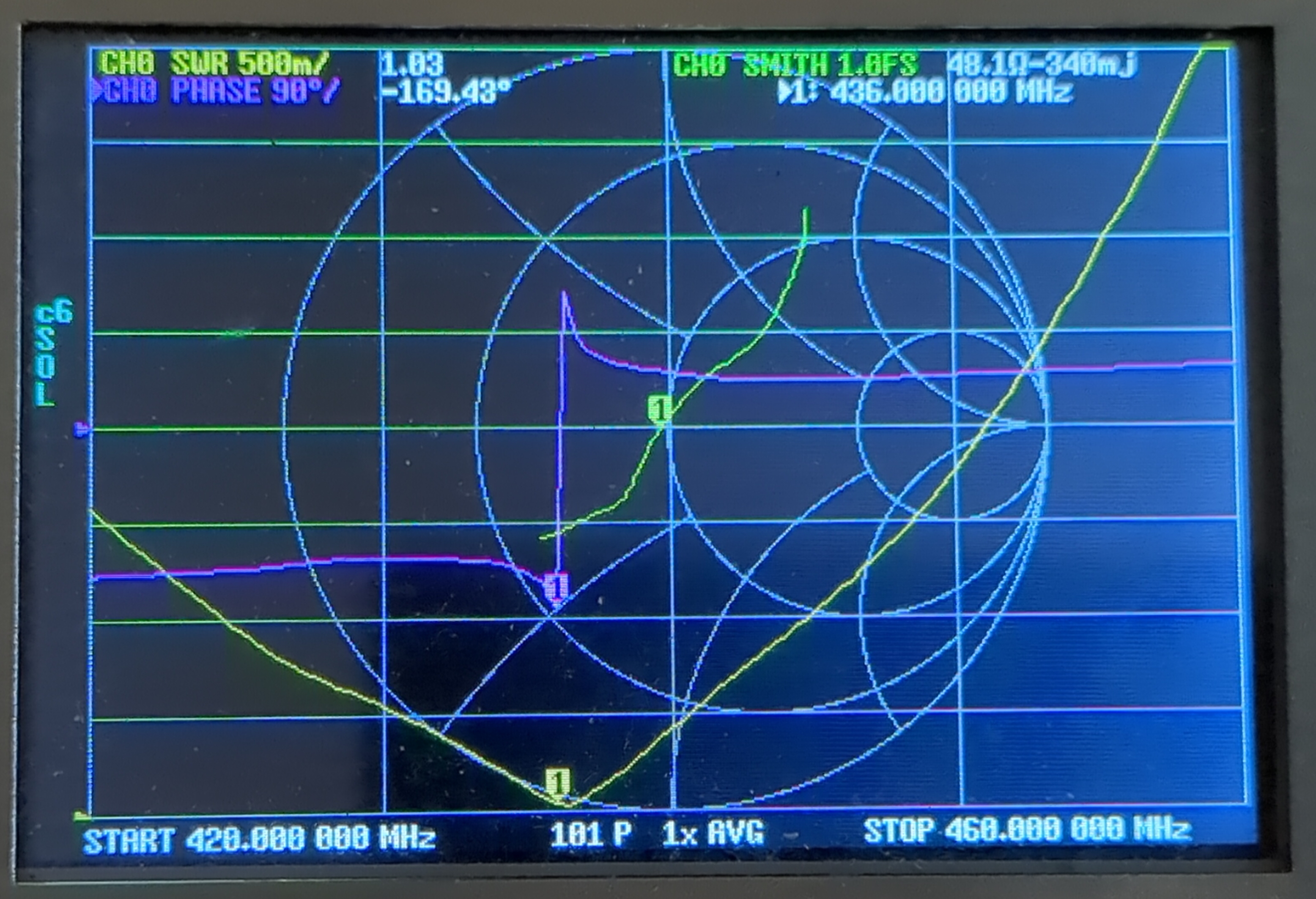
Both cover entire 70cm band under 1:1.5 SWR.
There's also 2m + 70cm duobander which is a compromise antenna:

Insides look similar but bigger. This time soldering didn't work, so instead it's a screwed connection between tinned coax and aluminum tube:

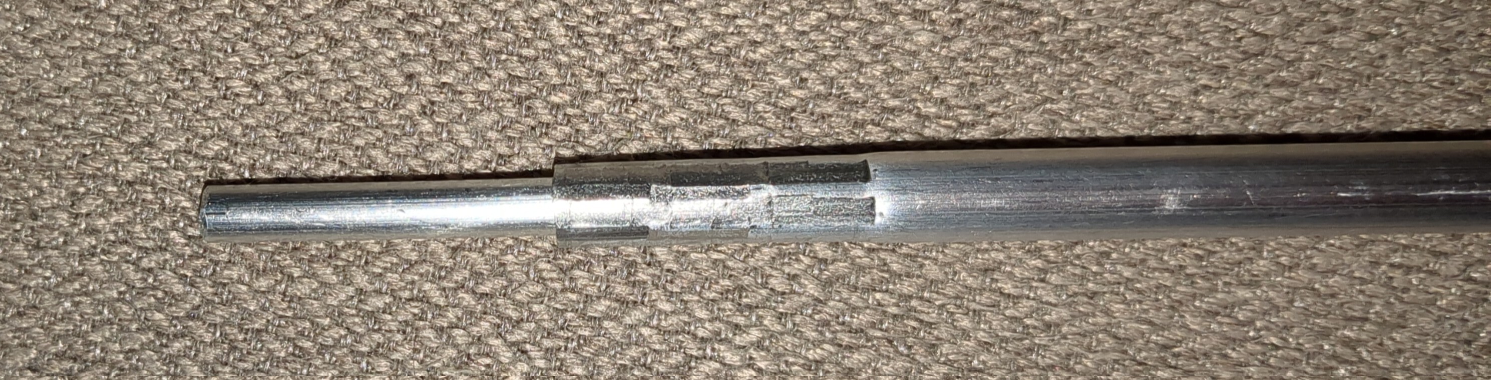
One annoyance was that 8mm dia 2m long aluminum tube as sold in hardware shop turned out to be a bit too short, so i had to extend it by crimping a bit of 5mm wire on both ends. It turned out decent, maybe even waterproof:
Despite extra diameter of tube, matching section got uncomfortably wobbly, so I've added crossties like suggested for ladder line:

Straight 3/2 wavelength long dipole radiates most of power in two cones directed towards ends of the wire, so while SWR on 2m band J-pole might be okayish on 70cm, radiation pattern will suffer greatly. The hook looking part is positioned so that between end of matching section and lower end of hook there's halfwave long section of wire, and hook itself is quarterwave long. The purpose of it is to stop 70cm current from propagating upwards. Radiation pattern was not tested, but this type of construction appears on internet. This is how it works:
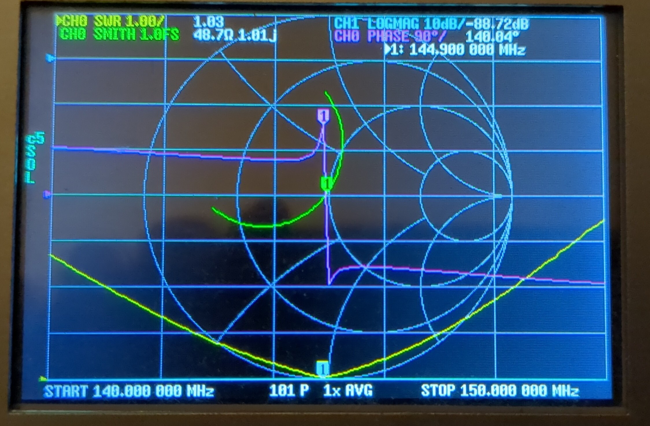
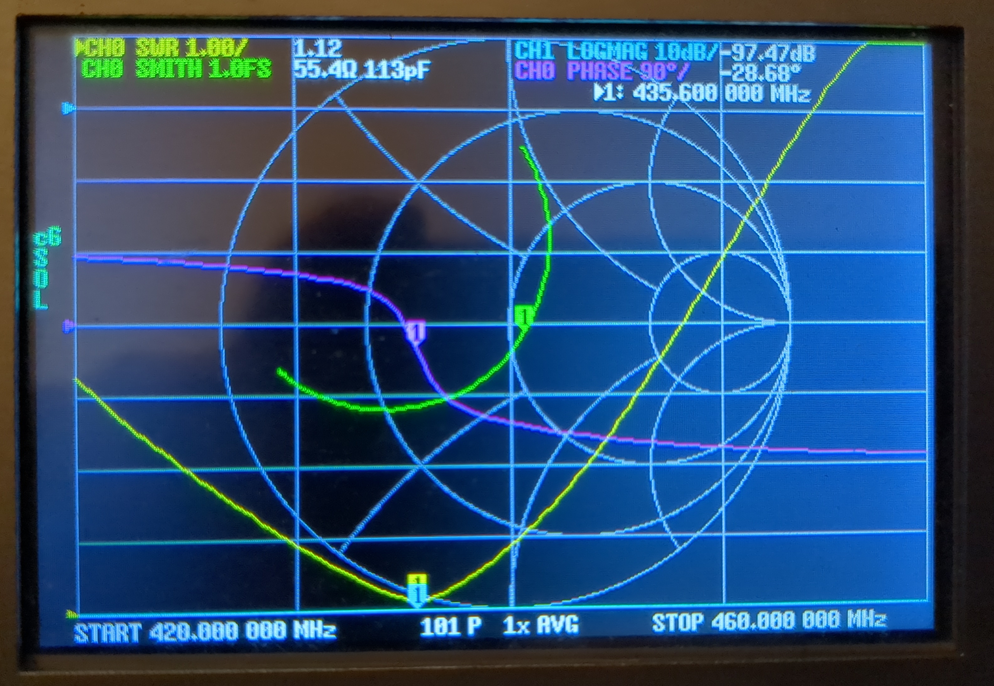
Easily covers entire 2m band and a section of 70cm band under 1:1.5 SWR (but all of 70cm band under 1:2 SWR)
Internet recommendations include making J-poles out of 300 or 450 ohm transmission line. Long time ago I've made one from 50 ohm coax and it worked, but was extremely narrowband. This is because J-pole matching section is shorter-than-quarterwave section of transmission line which turns real impedance into complex capacitive, and an inductor made out of shorted line on the other side. Put another way, it looks a bit like a beta match. The closer we get to almost-quarterwave transmission line transforming impedance to what we need, the less beta match like section has to sweat in order to get a match. Taking 5000 ohm as an impedance of end-fed antenna (irl it varies depending on many factors) and looking at smith chart, i've got this:
for 145MHz center frequency, 1:2 SWR bandwidth, by matching section impedance:
Above 500 ohm, it is not possible to find a good match. Real life impedances of radiating section of J-pole are probably complex, additionally opposite of what we see normally slightly longer antenna is capacitive instead of inductive like we see with center-fed halfwave dipole so maybe this also changes how things behave, because these antennas have bandwidth a bit wider than calculated using these approximations. Wider wire or tube will also make impedance of halfwave element lower, which means that impedance of matching section will be also lower while keeping width reasonable, but this is fine because optimum impedance of transmission line is also lower in this case. Thickness of elements and therefore required distance might become a mechanical problem for longer wavelengths, like lower VHF or 10m
J-pole is an unbalanced antenna, fed by balanced line, fed by unbalanced line. It needs some kind of balun at feedpoint. Here I've just used a ferrite bead and it seems to work good enough, but other people used sleeve baluns (like in copper cactus type antennas) and at least once i've seen folded balun (aka Pawsey stub). In either case shorting bar at the bottom should remain unconnected to anything, because this will cause problems with radiation pattern. People smarter than me elaborated on that https://www.hamradio.me/antennas/mast-mountable-j-pole-antenna.html